Building this kit was good exercise; if it works properly when I try it out in the field it will be entirely due to the truly excellent and detailed instructions that I downloaded and printed from the QRPguys website! Get ready for lots of pictures and discussion as we go through the process!
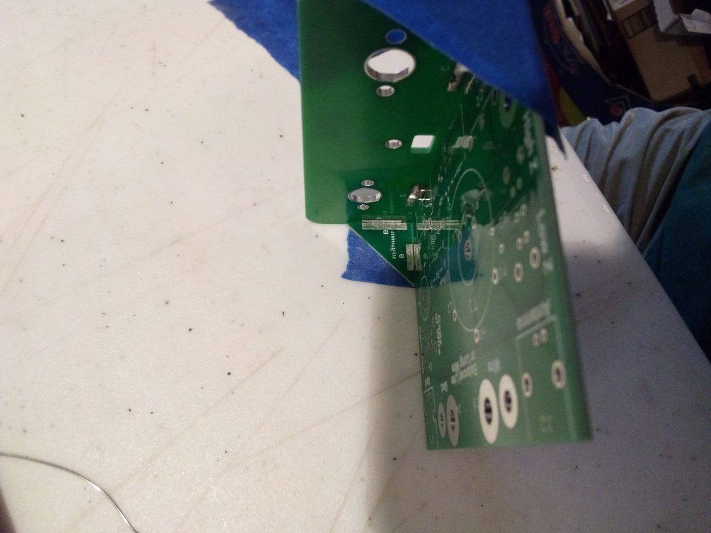
The whole tuner is built on a “chassis” assembled around the main circuit board, with a front panel and its two supporting gussets. All of them have strategically placed solder pads to hold them together. Here is the first place where the instructions really shine; they explain in detail precisely how to achieve a perfect result.
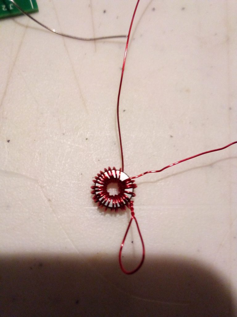
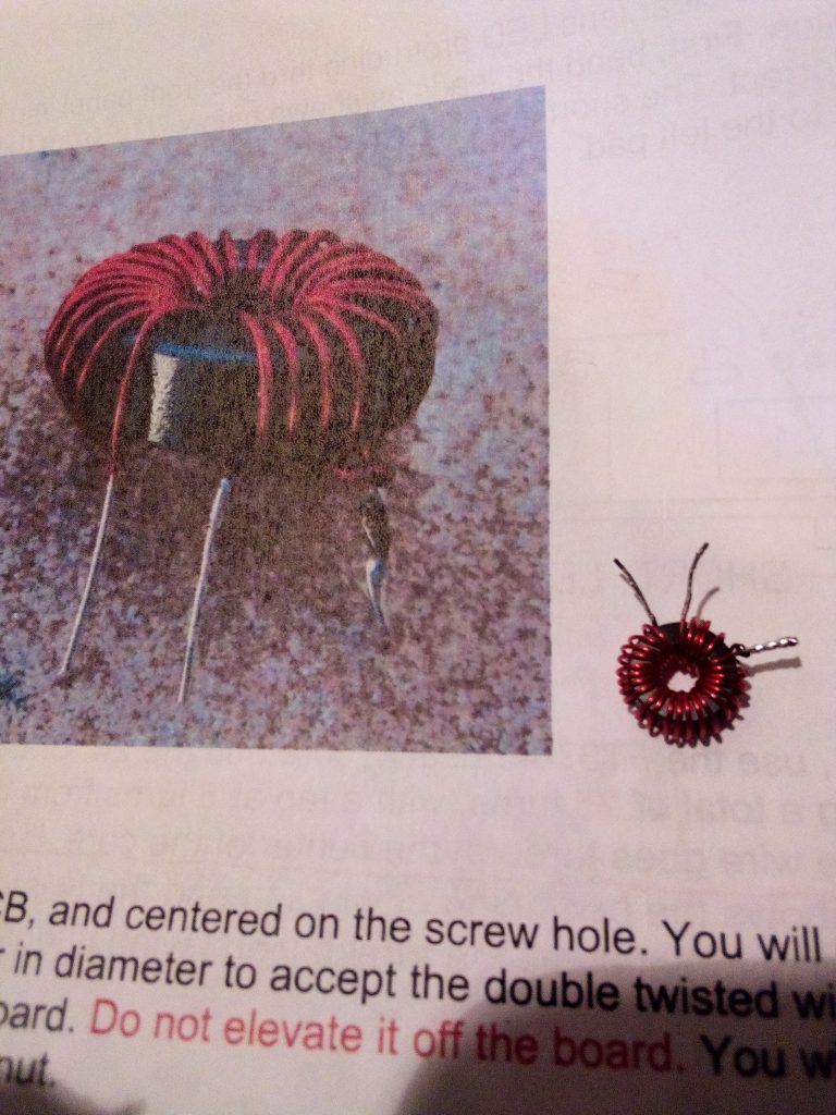
Placing the through-hole components was also simple and easy; but then came The Winding of the Toroids … the little one was not so bad, 25 turns, one tap. Again, the detailed instructions were crucial to my success. For the common case of losing count somewhere in the middle, they advise taking a photograph and viewing it enlarged on a screen, and this did in fact make for an easy recovery when I lost count!
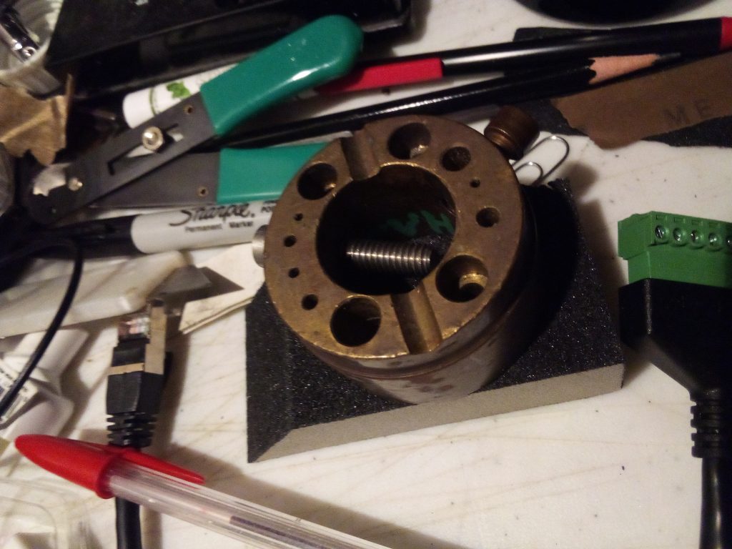
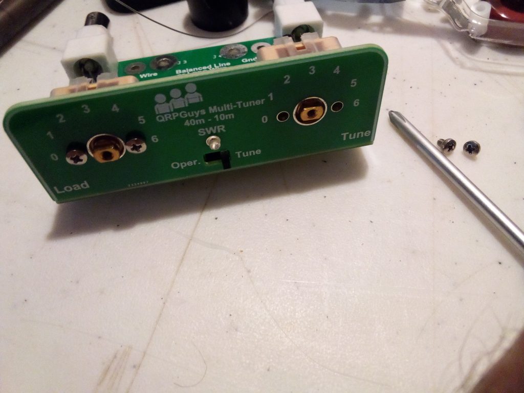
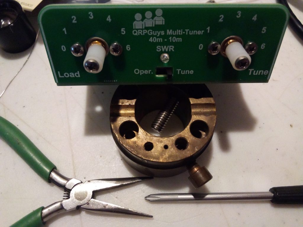
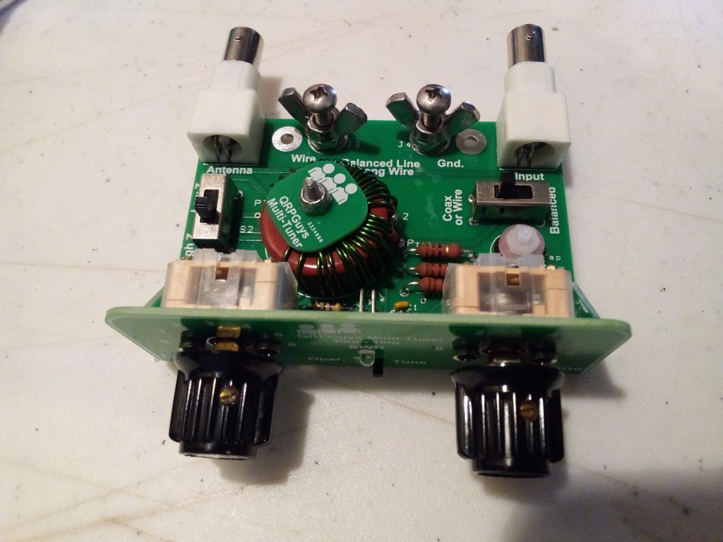
Now for a few more components, like the variable capacitors and BNC connectors, two of each. Not shown, the captive stainless steel wingnuts for connecting wire or balanced line.
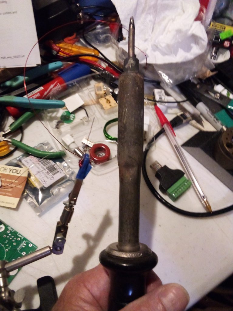
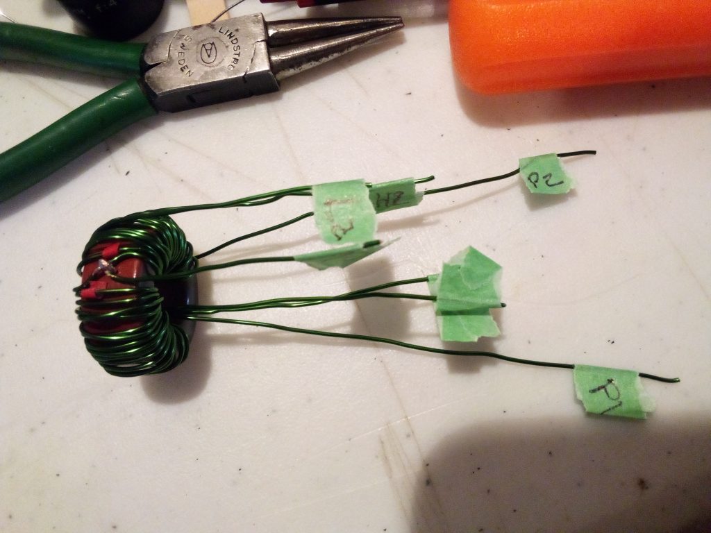
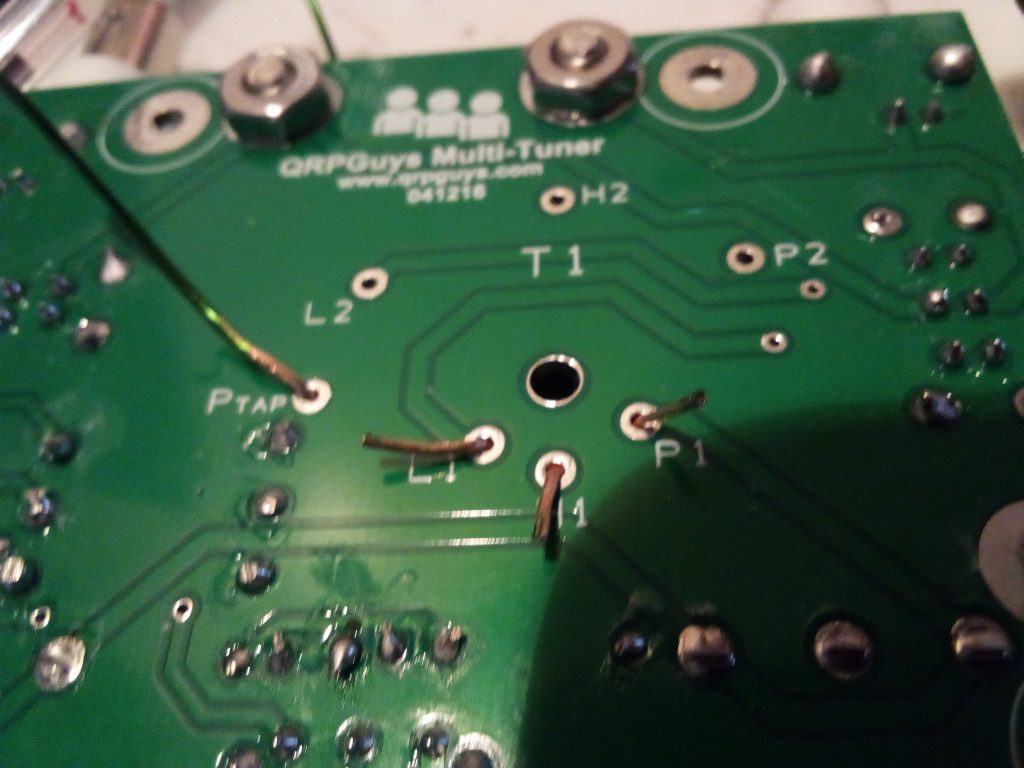
Which brings us to the last (but definitely not least) part: winding and installing the big toroidal transformer. Getting this crucial part right absolutely required every bit of the detailed instructions!
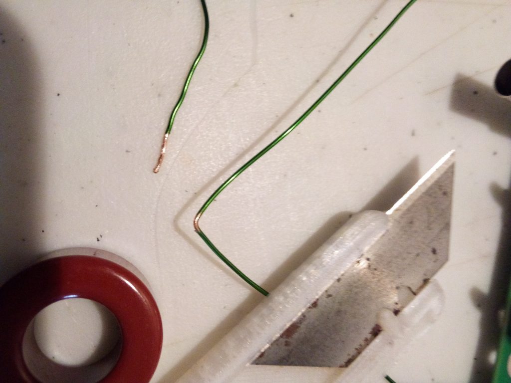
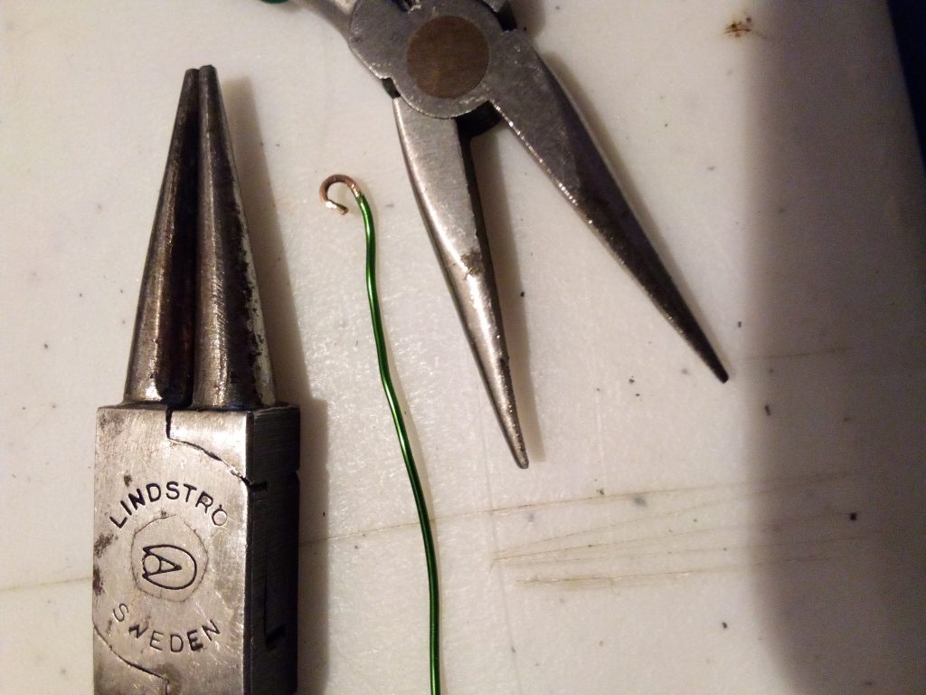
Doing the three windings correctly (using measured lengths of wire, all wound in the same direction from a center point) really required all of my attention and I took no pictures of intermediate stages as a result of that focus.
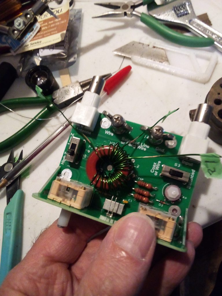
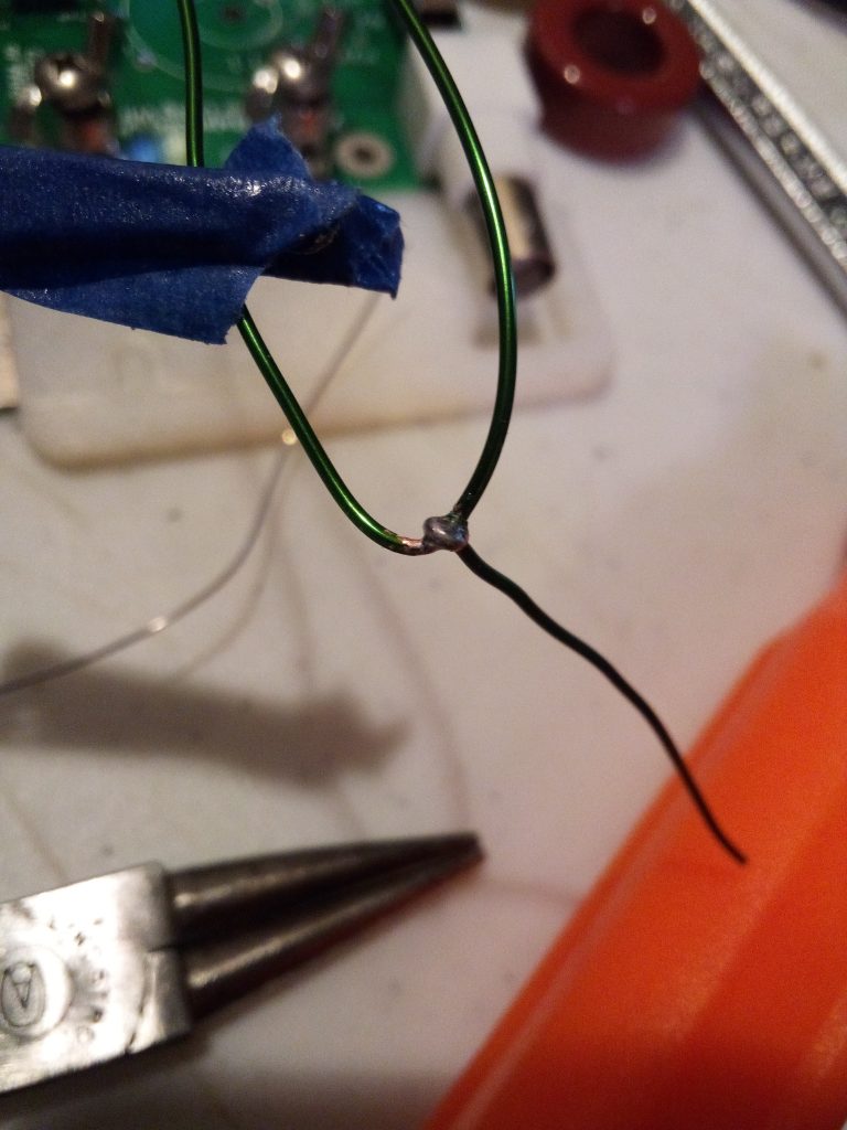
And when I clipped off the excess length of the last soldered lead, it was done. A gentle bath with rubbing alcohol and a toothbrush to remove rosin flux, stick on the 4 little rubber feet, and it’s ready to go!
Coming soon, build reports on the other two kits, and then some evaluation on the bench and in the field. Thanks for coming to driftlessqrp to read this, I hope you will come back for more!
Comments
One response to “Building the QRPguys Multi-Z tuner kit”
As I web-site possessor I believe the content material here is rattling fantastic , appreciate it for your efforts. You should keep it up forever! Good Luck.