Building The Kit !
Okay, I cheated a little; instead of clearing my worktable, I moved a few tools downstairs and built the kit on the kitchen table.
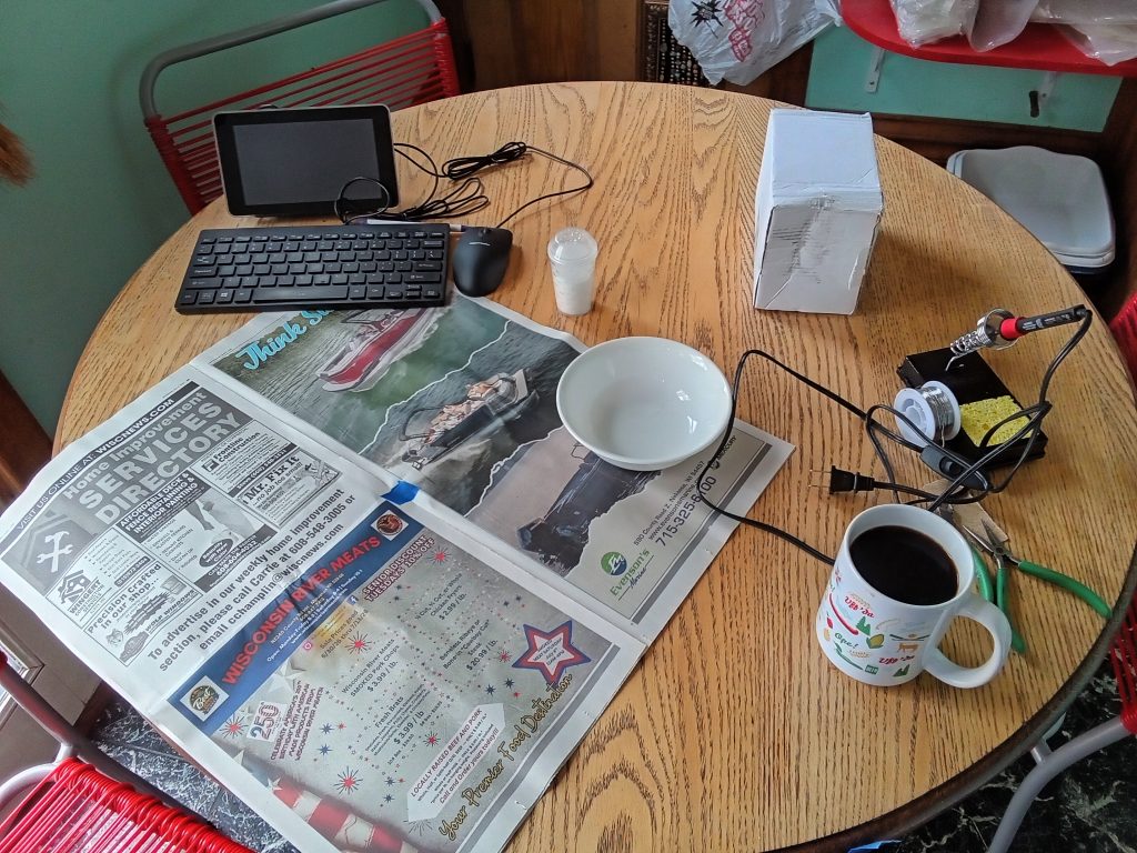
I used the Raspberry Pi to view the assembly instructions, located here. I recommend using this document rather than the YouTube video, the information there is fresher and reflects things recently learned in development. One of the inductors should be wound with 9 turns rather than 10 for better efficiency, and there are other useful tips as well.
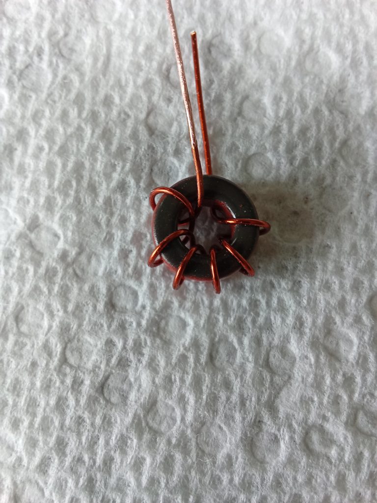

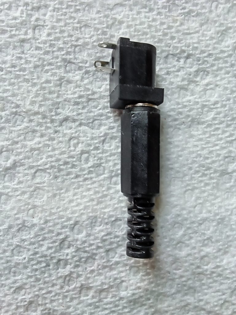
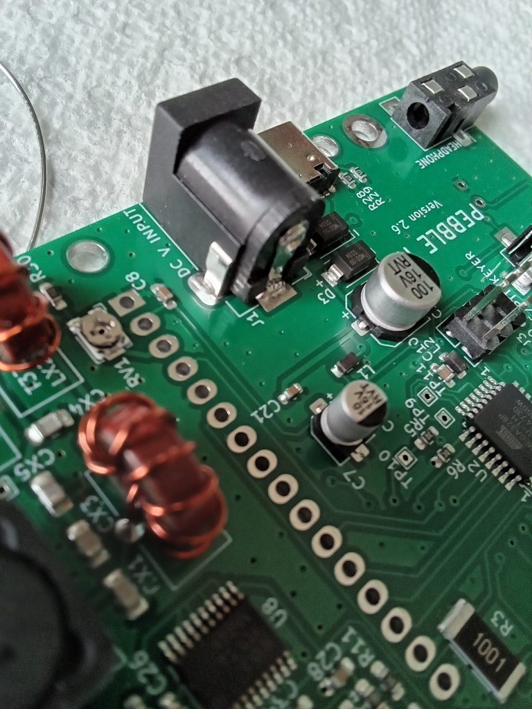
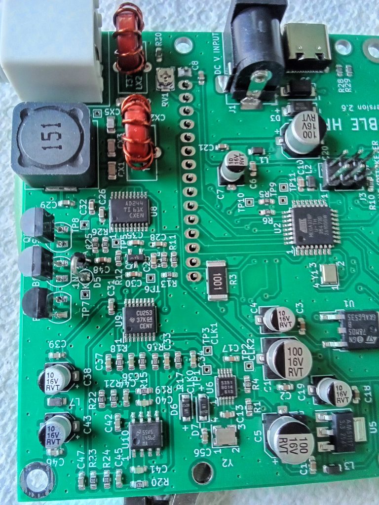
The diode is a 1N4756 Zener diode which provides overvoltage protection (under high SWR conditions) for the BS170 final amplifier transistors, a very nice design refinement!
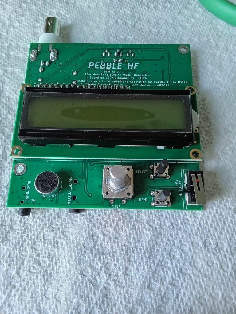
I needed to slightly bend the mounting tabs of the encoder to get it into the board; everything else fit the holes almost perfectly.
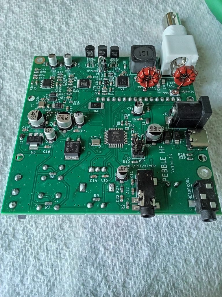
Okay, it’s all together; visually checked all the solder joints (for the 2nd or 3rd time), made a power cord, it’s time for the final, and most crucial, step;
THE SMOKE TEST !
The first time powering it up scared me; the LCD display lighted up, but the display was blank! Unplug! Quickly! Then I remembered the LCD contrast setting. (I think I have had this scare before with Arduino projects I have built, now that I think about it.)
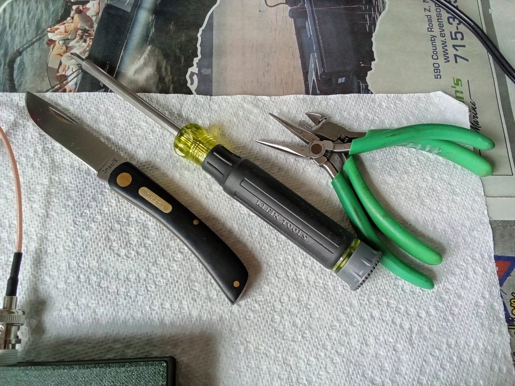
After trying a few different screwdriver bits to address the rather minimal user interface I settled on a #1 Philips to fit the tiny potentiometer that I pointed out above, then powered it up again. Twiddled the adjustment for optimal contrast and there’s a display, just like the pictures!
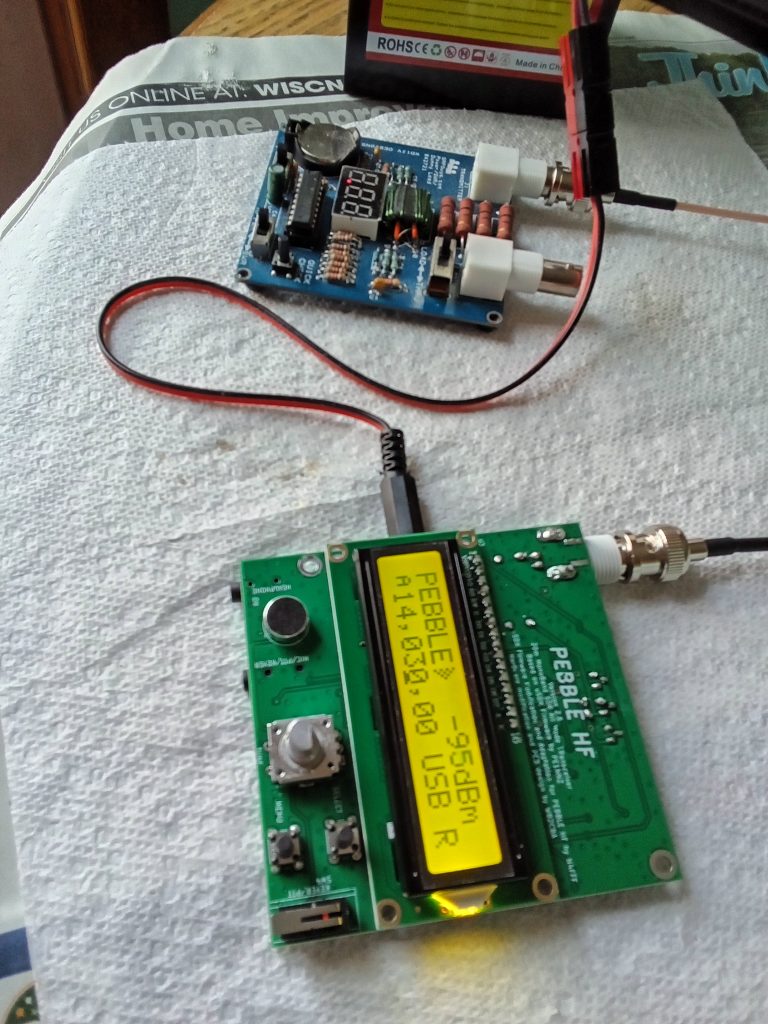
I’m going to say it again: PASSED THE SMOKE TEST ! SUCCESS !
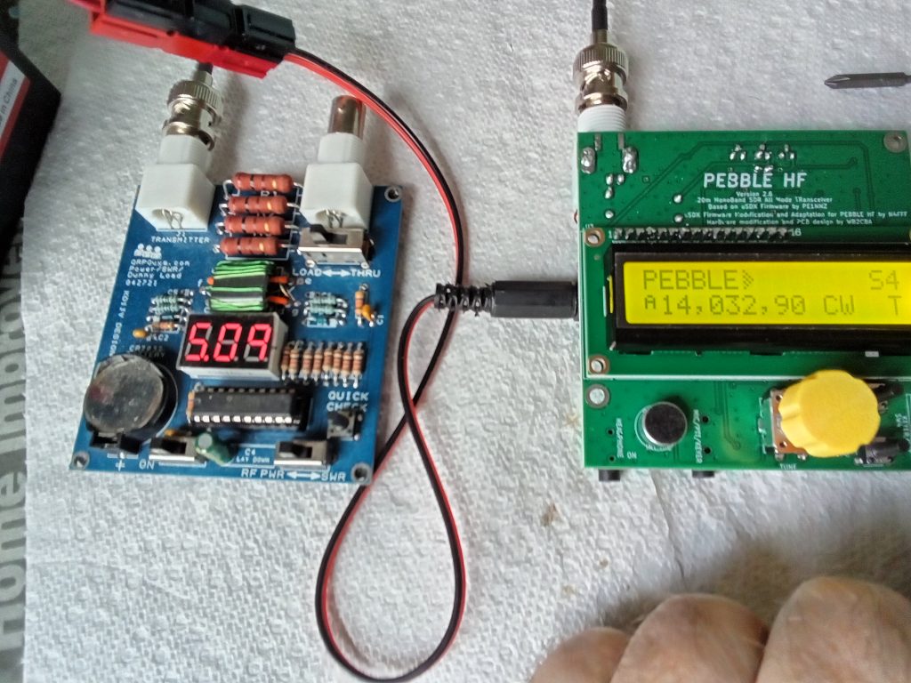
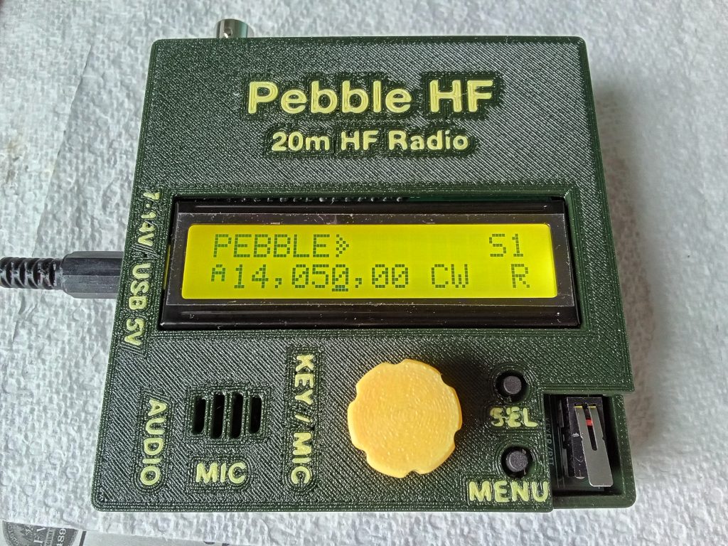
Haven’t hooked it up to an antenna to test the receiver, yet. Tomorrow.
The menus are familiar, since the firmware is modified from the USDX
Tomorrow I will check the receiver operation, and maybe try it out on the air.
Thank you for visiting driftlessqrp! More soon!